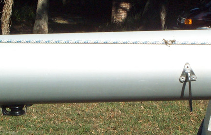
PHOTO 1 - Top of the mast is to the left. The block is mounted 2 ft down from the top of the aluminum section of the mast (not from the top of the casting in the mast). The spinnaker halyard ring is mounted 1 foot below the block, or 3 ft from the top of the mast.
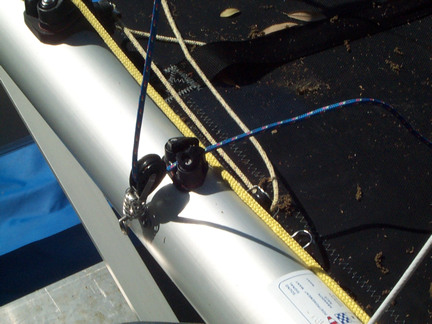
PHOTO 2 - The halyard runs down the mast through a spring block and into a small cleat. The fairlead on the top of the cleat has been cut away to reduce the chance of the halyard being caught during release. Another method is to install a block on the mast.
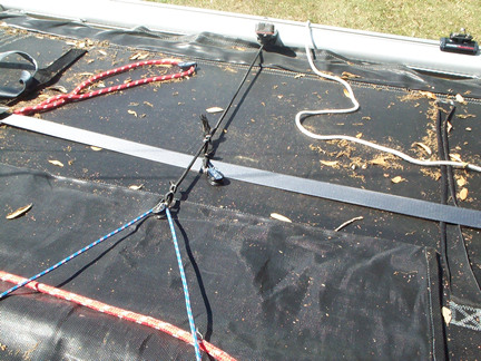
PHOTO 3 - The halyard then runs (coming from the left side in the pic) aft to a block on a bungee which is attached to the rear crossbeam. This helps keep the line from becoming tangled. (Note the second block on the bungee which is used for the spinnaker sheet for the same purpose.)
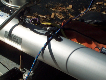
PHOTO 4 - The halyard then runs continuously through a fairlead attached to the front crossbeam. In the lower left the snuffer pole is seen and the snuffer bag is attached to it (not seen). After going through the fairlead the halyard runs into the end of the snuffer bag and along the length of the inside of the bag, exiting through the other end of the bag at the snuffer ring.
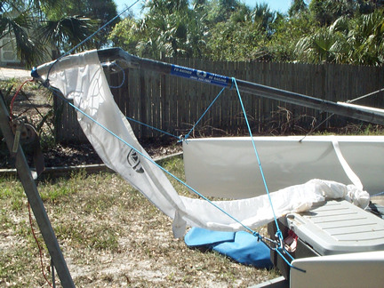
PHOTO 5 - After exiting the spinnaker bag the halyard runs through the bellycord grommets on the spinnaker and is terminated in the top grommet of the sail. Also from this photo the overall layout of the snuffer pole support lines can be seen. There are a total of three lines, one each from a hull to the snuffer ring, and the third supporting the snuffer pole (note this line wraps around the pole three times).
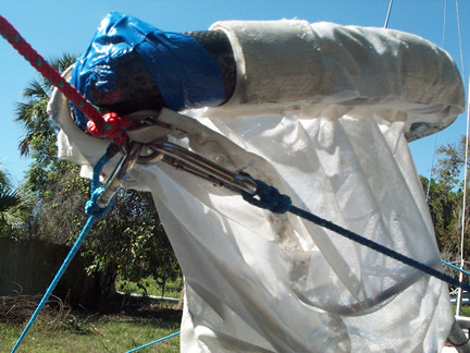
PHOTO 6 - The snuffer ring has an eyebolt mounted with the eye facing down. The support lines from the hull mount directly to the eyebolt Also note the red line, which is used to attach the tack point of the spinnaker to the snuffer. Be sure to tape the nut on the top of the eyebolt
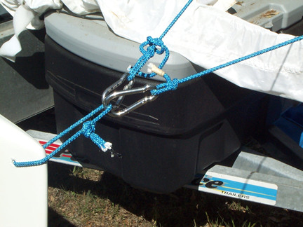
PHOTO 7 - The support lines attachment point to the hull is shown. A hole must be drilled in the upper corner of the hull and its a good idea to point some glass or epoxy on the inner walls of the hole.
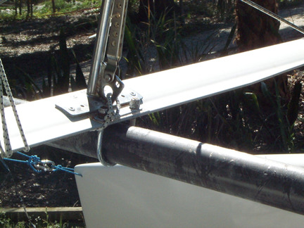
PHOTO 8 - Two holes are drilled through the foil and a U-bolt is used to support the snuffer pole by the foil. Although not shown, this area can be wrapped in tape to reduce wear.
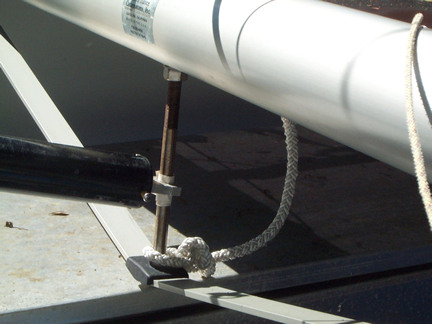
PHOTO 9 - The snuffer pole attachment point. This is a custom piece that pretty much any machine shop can make which clamps around the striker rod and has a rod sticking out of it which goes into the hole on the snuffer pole.
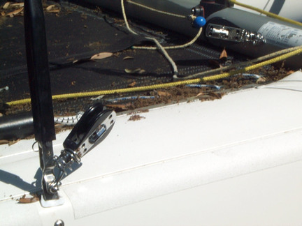
PHOTO 10 - The spinnaker sheets! The sheets attach to the clue of the sail and run aft on each side of the boat to a corresponding spring mounted ratchamatic block on each side shroud. There are port and starboard versions of these blocks which allow for the switch to face up.
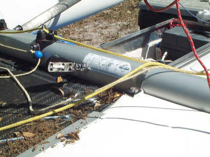
PHOTO 11 - From the side shroud block the sheet then runs to another spring mounted ratchamatic block on the front crossbeam (seen on the lower left hand corner of the course sticker). The sheet then runs aft to the bungee mounted block shown in photo 3 and continues in reverse on the other side of the boat.
Dated info about a spinnaker purchase option from the original site has been removed